
Product Description
The CAN bus to fiber optic switch provide an optical point-to-point or bus network connection for CAN bus data interfaces on one or two, multimode or single mode optical fibers. The CAN bus fiber optic converter has 1 CAN port and 1 fiber optic port, CAN port is configurable via software.The Can bus series units support both CAN 1.0 and CAN 2.0B CAN standards and are transparent to all high level protocols.It can solve the problem of CAN bus’s cascading problems,it can transmit 1MB data to 20km and the maximum is 6500 frames when it’s up to 20km distance,so it the most advanced CAN bus fiber optic converter.
Product Features
- Up to 1Mbps data rate (20km when it’s 1MB, New Technology)
- Up to 6500 frames/second
- Software Configurable
- Multi mode and Single mode
- Single fiber solution supported
- 5 year warranty
Specification
| CAN BUS | |
| Data Formats | CAN 1.0, CAN 2.0, Device Net |
| CAN Data Rate | 0-1 Mbps |
| Bit Error Rate | <1 x 10-12 |
| Connectors | |
| Data | Screw Block Terminal |
| Fiber | ST, SC or FC (ST fitted as standard) |
| Environmental | |
| Operating Temperature | -30C—+70C |
| Storage Temperature | -40C—+85C |
| Operating Humidity | 0-95% |
| MTBF | >100,000 Hours |
| Optical | |
| Fiber | Multi mode or Single mode |
| Wavelength | MM:850/1310nm, SM:1310/1550nm |
| Number of fibers | 2 or 1 |
| Power | |
| Power Input | +9 to +40V DC |
| Mechanical | |
| Dimensions | 156(W)x108(D)x33.6(H)mm Wall Mount & DIN Rail |
Model Selection
| Model Number | Description | Port No. | Fiber Mode | Fiber Connector |
|---|---|---|---|---|
| HFB-CAN-FO-P2S | Fiber Optic Converter,Point to Point Link,Dual Fiber, 2km,DIN Rail Mount | 1CAN+2 FO | Single mode | ST/SC/FC |
| HFB-CAN-FO-P2M | Fiber Optic Converter,Point to Point Link,Dual Fiber, 20km | 1CAN+2 FO | Multi mode | ST/SC/FC |
Enclosure

Panel 1

LED
| LED No | LED For | LED Name | LED Function |
|---|---|---|---|
| 1 | CAN0 | TX | Transmitting |
| 2 | RX | Receiving | |
| 3 | Error | Failure | |
| 1 | Fiber0 | TX | Transmitting |
| 2 | RX | Receiving | |
| 3 | Error | Failure |
Others
| Name | Relevant | Function | Remarks |
|---|---|---|---|
| Baudrate | CAN0 | Rotary button | Configure baud rate by button,fast configuration |
| RS232 | CAN0 | Console port | Configure baud rate by software on computer |
| VCC | V+ Power input | DC 9~40V, With SPD,RCP,OCP | |
| GND | V- Power input | DC 9~40V,With SPD,RCP,OCP |
Panel 2

| Port Name | Relevant | Function | Remarks |
|---|---|---|---|
| SYS | System LED | ||
| TX | Fiber0 | Transmit | Fiber optic connector TX |
| RX | Fiber0 | Receive | Fiber optic connector RX |
| CANH | CAN0 | CANH | CAN copper port |
| CANL | CAN0 | CANL | CAN copper port |
| R+ | CAN0 | R+ Terminal resistance | Not necessary in normal condition |
| FG | CAN0 | Grounding | Not necessary |
| R- | CAN0 | R- Terminal resistance | Not necessary in normal condition |
| SW0-SW2 | DIP Switch button | Button 1 on for 120Ohm resistance |
Installation Methods
- Switch off all power supply before installation.
- Connect the local “FTX” Fiber Optic to the remote “FRX” Fiber Optic, the local “FRX” to the remote “FTX”. And ensure that fiber is properly aligned to the receiving connector.
- Connect the “D+” Data of the Profibus+ and the “T–” Data to the Profibus-. Then screw down the bolt.
- On the bottom of the converter, there is a DIP Switch., When the D2 is “ON”,it’s connected to 120 Ohm terminal resistance.
DIP Switch setup table
| DIP Switch pin name | D1 | D2 | D3 |
| Setup State | OFF | OFF | OFF |
120 ohm Terminal Resistance
| DIP Switch pin name | D1 | D2 | D3 |
| Setup State | OFF | ON | OFF |
Baud rate rotary switch button setup table
| B0 Button Position | 9 | 8 | 7 | 6 | 5 | 4 | 3 | 2 | 1 | 0 |
|---|---|---|---|---|---|---|---|---|---|---|
| CAN Baud Rate | 80Kbps | 100Kbps | 125Kbps | 200Kbps | 250Kbps | 400Kbps | 500Kbps | 666Kbps | 800Kbps | 1000Kbps |
| A | B | C | D | E | F | |||||
| 50Kbps | 40Kbps | 20Kbps | 10Kbps | 5Kbps | configuration | |||||
Note: When the B0 is switched to F position, you can configure the baud rate through the serial DB9 port.
Configure the baud rate by software
Switch the “B0” button to F position and connect the straight line(NOT cross line) to the console port(DB9) and the other end of the line to the computer.
1.Open CANConfig and click“CAN FIB-100PT”,you will see 3 options: Basic Info,Baudrate and
Filter.

2. Software Configuration
- Open RS232:Communicate with the serial RS232.
- Read Parameter:Read all parameters of the device and display them.
- Write Parameter:Write all parameters into the device.These parameters will be stored to the flash and read them automatically when powers on.
3. Device Parameters
3.1 Basic InfoClick the “Open RS232” and read out all information by clicking “Read Parameter” button.The “Basic info” option contains the vendor ID,device type,device code,hardware version,software version and serial numbers.
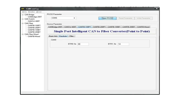
3.2 Baudrate
“Baudrate” is for setting up the baud rate of all channels of the device.When the rotary button is switched to”F” position,you can configure the baud rate on it.See the below figure and baud rate table
Common standard baud rate’s BTR0 and BTR1 values
| CAN Baud rate | BTR0(Time0-SJA1000) | BTR1(Time1-SJA1000) |
|---|---|---|
| 5Kbps | 0xBF | 0xFF |
| 10Kbps | 0x31 | 0x1C |
| 20Kbps | 0x18 | 0x1C |
| 40Kbps | 0x87 | 0xFF |
| 50Kbps | 0x09 | 0x1C |
| 80Kbps | 0x83 | 0Xff |
| 100Kbps | 0x04 | 0x1C |
| 125Kbps | 0x03 | 0x1C |
| 200Kbps | 0x81 | 0xFA |
| 250Kbps | 0x01 | 0x1C |
| 400Kbps | 0x80 | 0xFA |
| 500Kbps | 0x00 | 0x1C |
| 666Kbps | 0x80 | 0xB6 |
| 800Kbps | 0x00 | 0x16 |
| 1000Kbps | 0x00 | 0x14 |

How to use the filter function:
- Select the channel that needs filter function from the sub list of“Port”.
- Select “Filter Enable”and you can revise the content of the filter.
- Select the frame type(Standard or extended frame types) from the “Frame Type” .
- On “Start ID”and“End ID” rows,please fill in the ID of the frame that you want to filter.The standard frame range is 0~2047(0x7FF)and the extended frame range is 0~536870911 (0x1FFFFFFF).
- After setting up the frame’s filter parameters,please click“Write Parameter” button and write the router parameters into the device,then it’s valid.
Installation Applications

Dimensions (mm)
