485-FO-M4M
Product Description
The Multi-Drop Bus Fiber Optic Modem series products provide an optical bus network for RS-232, RS-422 or RS-485 data interfaces over a pair of multi mode or single mode optical fibers. The Terminal module units operate as the end or terminal points and provide an electrical connection and a two fiber optical connection. The Repeater module units act as in-line repeater stations and provide a single electrical connection and two optical connections, one upstream and one downstream . This series is available in either wall mount, DIN rail or 2U chassis card configurations.
Product Features
- Multi protocol data interface
- Switchable termination and biasing
- Multi mode and single mode
- Single or dual redundant power supply
- 5 years warranty
Specification
| RS-485 | |
| Data Formats | RS232,RS422,RS485 |
| RS232 Data Rate | 115.2kbps |
| RS422/485 Data Rate | 512kbps |
| Bit Error Rate | <1 x 10-12 |
| Connectors | |
| Data | Screw Block Terminal |
| Fiber | ST, SC or FC (ST fitted as standard) |
| Environmental | |
| Operating Temperature | -30C—+70C |
| Storage Temperature | -40C—+90C |
| Operating Humidity | 0-95% |
| MTBF | >100,000 Hours |
| Optical | |
| Fiber | Multi mode or single mode |
| Wavelength | MM:850nm,SM:1310nm |
| Number of fibers | 4 or 2(WDM,Bi-Di) |
| Power | |
| Power Input | AC 220V 110v or DC+110V ,+5V ,+12V ,+24V, +48V Option |
| Mechanical | |
| Dimensions | 43(W)×88.5(D)×124.5(H)mm DIN Rail |
Model Selection
| Model Number | Description | Fiber No. | Fiber Mode | Fiber Connector |
|---|---|---|---|---|
| FM-485-FO-M4M | Multi Drop Link,4 Fiber, 2km | 4 | Multi mode | ST/SC/FC |
| FM-485-FO-M4S | Multi Drop Link,4 Fiber, 20km | 4 | Single mode | ST/SC/FC |
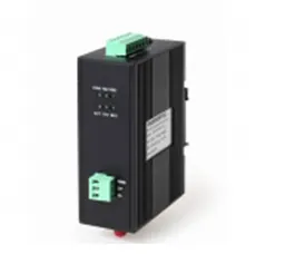
Enclosure

LED Indicators:POW:
Power Supply On if Power input is OK
ACT: RS-485 Data transmit/receive Flashing if there is activity
TX1: The 1 Channel Transmit Fibre Link Flashing if there is activity
RX1: The 1 Channel Receive Fibre Link Flashing if there is activity
TX2: The 2 Channel Transmit Fibre Link Flashing if there is activity
RX2: The 2 Channel Transmit Fibre Link Flashing if there is activity
D+: Connect RS-485+ or Line A
D-: Connect RS-485+ or Line B
GND: GND of RS-485

V-: DC24V+
V+: DC24V-
GND: No Connection

Fiber Connectors
FTX1: Fiber Optical ST of the 1 channel ( transmit & receive )
FRX1: NONE
FTX2: Fiber Optical ST of the 2 channel ( transmit & receive)
FRX2: NONE
Caution
- Switch off all power supply before installation
- Ensure fiber is properly aligned to the receiving connector
- Do NOT stare at the fiber core
- On the bottom of the product, there is a DIP Switch, the users should setup the DIP Switch according to the selecting mode.
DIP Switch setup table
| DIP | D1 | D2 | D3 |
| STATE | OFF | Terminal
Resistance (120Ω) |
OFF |
Install Applications
Figure 1 Multi-Drop Bus
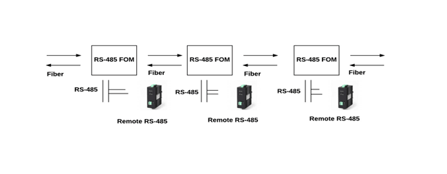
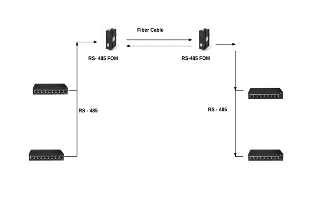
Figure 2 Point to Point (Trunk Line)
Dimensions (mm)
