485-FO-P2M
Product Description
The RS-485 fiber optic modem(Point to point) use the most advanced digital technologies to provide excellent repeatable performance for today’s data systems. It supports transmission of one bi-directional data channel over one multimode or single mode optical fiber. RS232, RS422 and RS485 standards are fully supported. The plug-and-play design ensures ease of installation with no electrical or optical adjustment needed. LED indicators are provided to show the operational status of the unit clearly. The series is available in compact wall mount or 2U chassis card. The RS-485 Series converter is equipped with a multiple interface circuit that can handle RS-485 serial interfaces and multi-mode or single mode fiber. RS-485 fiber converters are used to extend serial transmission distance up to 2 km (multi-mode fiber) or up to 20-100km (single mode fiber). .Auto Baud Rate Detection The RS-485 Series incorporates a method for automatically detecting the serial signal baud rate by hardware. This is an extremely convenient feature for the user. Even if a device’s baud rate is changed, the signal will still be transmitted through the RS-485 to fiber converter without any problem.
Product Features
- Single or dual redundant power supply
- Multimode and single mode solutions
- Switchable 120Ω termination and biasing
- LED indicators provide quick diagnosis of all important system parameters
- Up to 14 units in a 2U chassis
- Compact and 2U chassis card configuration
Specification
| RS-485 | |
| Data Formats | RS232,RS422,RS485 |
| RS232 Data Rate | 115.2kbps |
| RS422/485 Data Rate | 512kbps |
| Bit Error Rate | <1 x 10-12 |
| Connectors | |
| Data | Screw Block Terminal |
| Fiber | ST, SC or FC (ST fitted as standard) |
| Environmental | |
| Operating Temperature | -30C—+70C |
| Storage Temperature | -40C—+90C |
| Operating Humidity | 0-95% |
| MTBF | >100,000 Hours |
| Optical | |
| Fiber | Multi mode or single mode |
| Wavelength | MM:850nm,SM:1310nm |
| Number of fibers | 2 or 1(WDM, Bi-Di) |
| Power | |
| Power Input | AC 220V 110v or DC+110V ,+5V ,+12V ,+24V, +48V Option |
| Mechanical | |
| Dimensions | 43(W)×88.5(D)×124.5(H)mm DIN Rail |
Model Selection
| Model Number | Description | Fiber No. | Fiber Mode | Fiber Connector |
|---|---|---|---|---|
| FM-485-FO-P2M | Point to point Link,Dual Fiber, 2km | 2 | Multi mode | ST/SC/FC |
| FM-485-FO-P2S | Point to point Link,Dual Fiber, 20km | 2 | Single mode | ST/SC/FC |
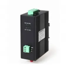
Enclosure

LED Indicators:
POW: Power Supply On if Power input is OK
TXD: The Transmit Fibre Link Flashing if there is activity
RXD: The Receive Fibre Link Flashing if there is activity
D+: Connect RS-485+ or Line A
D-: Connect RS-485+ or Line B
GND: GND of RS-485

V-: DC24V+
V+: DC24V-
GND: GND of DC
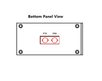
Fibre Optic Connectors
FTX: Transmitter (Fibre Optic ST)
FRX: Receiver (Fibre Optic ST)
Install Methods
- Switch off all power supply before installation.
- Connect the local “FTX” Fiber Optic to the remote “FRX” Fiber Optic, the local “FRX” to the remote “FTX”. And ensure that fiber is properly aligned to the receiving connector.
- Connect the “D+” Data of the Profibus+ and the “T–” Data to the Profibus-. Then screw down the bolt.
- On the bottom of the converter, there is a DIP Switch., When the D2 is “ON”,it’s connected to 120 Ohm terminal resistance.
DIP Switch setup table:
| DIP Switch pin name | D1 | D2 | D3 |
| Setup State | OFF | OFF | OFF |
120 ohm Terminal Resistance
| DIP Switch pin name | D1 | D2 | D3 |
| Setup State | OFF | ON | OFF |
Install Applications

Dimensions (mm)
