Product Description
The LonWorks Fiber Optic Modem is a Field bus Control System (FCS). Our Fiber Optic Modem uses the fiber cable as its transmission medium and utilizes Optical Fiber modulation/demodulation technology to changes the electric medium into a light medium transmission. The LonWorks Fiber Optic Modem product eliminates many of the disadvantages of copper cable. Examples of these disadvantages are EMI/RFI, ground loops (electrical isolation with fiber), high attenuation (high signal loss), short transmission distance between nodes of a system, and potential lightning damage. The LonWorks Fiber Optic Modem can be widely used, such as Industrial Controls, Intelligent Transportation Systems (ITS), Industrial Networking, Supervisory Control and Data (SCADA) and so on.
Specification
| LonWorks | |
| Connectors | Terminal |
| Standard | LonWorks(LonTalk) |
| Data Rate | 78.6Kbps |
| Extended Distance | 2.7Km |
| Optical | |
| Number of Fibers | 2 |
| Wavelength | 850/1310nm |
| Fiber Type | 62.5/125µm(MM), 9/125µm(SM) |
| Distance | 0~3KM or 0-20 KM |
| Connector Type | ST/PC |
| General | |
| Operating Temperature | -30~70˚C / -30 ~ +158ºF |
| Operating Humidity | 0 ~ 95% non-condensing |
| Mean Time Between Failure (MTBF) | > 70,000hrs |
| Power Supply Adaptor | DC24V |
| Dimensions (W×H×D) | 124.5×43×88.5mm |
Model Selection
| Model Number | Description | Fiber No. | Fiber Mode | Fiber Connector |
|---|---|---|---|---|
| FM-Lon-FO-P2M | Point to point Link,Dual Fiber, 2Km | 2 | Multi mode | ST/SC/FC |
| FM-Lon-FO-P2S | Point to point Link, Dual Fiber, 20Km | 2 | Single mode | ST/SC/FC |
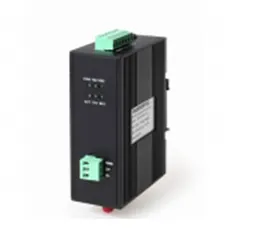
Enclosure

LED Indicators:
POW: Power Supply On if Power input is OK
TXD: The Transmit Fibre Link Flashing if there is activity
RXD: The Receive Fibre Link Flashing if there is activity
Data Input
D+: Connect LON A
D-: Connect LON B
GND: NONE

V-: Connect DC24V power supply “-“
V+: Connect DC24V power supply “+”
GND: Power Ground
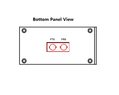
Fibre Optic Connectors
FTX: Transmitter (Fibre Optic ST)
FRX: Receiver (Fibre Optic ST)
Installation Methods
- Switch off all power supply before installation.
- Connect the local “FTX” Fiber Optic to the remote “FRX” Fiber Optic, the local “FRX” to the remote “FTX”. And ensure that fiber is properly aligned to the receiving connector.
- Connect the “D+” Data of the Profibus+ and the “T–” Data to the Profibus-. Then screw down the bolt.
- On the bottom of the converter, there is a DIP Switch., When the D2 is “ON”,it’s connected to 120 Ohm terminal resistance.
DIP Switch setup table:
| DIP Switch pin name | D1 | D2 | D3 |
| Setup State | OFF | OFF | OFF |
120 ohm Terminal Resistance
| DIP Switch pin name | D1 | D2 | D3 |
| Setup State | OFF | ON | OFF |
Installation Applications

Dimensions (mm)
